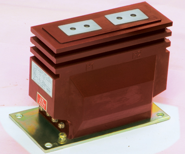
One minute understanding of current transformers
A current transformer is an instrument that converts high primary current into low secondary current based on the principle of electromagnetic induction for measurement. A current transformer is composed of a closed iron core and winding. Its primary winding has very few turns and is connected in series in the circuit where the current needs to be measured. The principle of current transformer is based on the principle of electromagnetic induction. A current transformer is composed of a closed iron core and winding. Its primary winding has very few turns and is connected in series with the line that needs to measure the current, so it often has all the current flowing through the line. The secondary winding has a relatively large number of turns and is connected in series with the measuring instrument and protection circuit. When the current transformer is working, its secondary circuit is always closed, so the impedance of the measuring instrument and protection circuit series coil is very small, and the working state of the current transformer is close to a short circuit.
The M8 type current transformer from Shenzhen Weikewei Technology Company has a small primary current and is commonly used in relay protection circuits. It is suitable for small spaces such as low-voltage drawer cabinets. Used for collecting low-voltage overload and short circuit signals, and used in conjunction with protective relays and motor protectors.
1、 Function of current transformer
The main function is to convert high currents in AC circuits into small currents with a certain ratio of 62616964757a686964616Fe78988e69d8331333366303839 (China's standard is 5 amperes) for measurement and relay protection purposes only. In the process of power generation, transformation, transmission, and distribution, due to the different electrical equipment used, the current often ranges from tens of amperes to tens of thousands of amperes, and these circuits may also be accompanied by high voltage.
So in order to monitor and measure the circuits of these lines, while also addressing the dangers posed by high voltage and high current, current transformers are needed. The clamp meter used by electricians is a device used to measure alternating current, and its "clamp" is a through type current transformer.

2、 Working principle of current transformer
58彩票The principle of a current transformer is based on the principle of electromagnetic induction. Its primary winding often has all the current of the line flowing through it. When the current transformer is working, its secondary circuit is always closed. Therefore, the impedance of the measuring instrument and the protection circuit connected in series with the coil is very small, and the working state of the current transformer is close to a short circuit.
In an ideal current transformer, if it is assumed that the no-load current I0=0, the total magnetic potential I0N0=0. According to the law of conservation of energy, the magnetic potential of the primary winding is equal to that of the secondary winding, that is, I1NI=- I2N2
The current of a current transformer is inversely proportional to its number of turns, and the ratio of primary current to secondary current I1/I2 is called the current ratio of the current transformer. When the secondary current is known, the primary current can be calculated by multiplying it by the current ratio. At this point, the phasor of the secondary current differs from that of the primary current by 1800.
3、 Principles for the use of current transformers
1. In order to meet the needs of measuring instruments, relay protection, circuit breaker failure judgment, and fault filtering devices, 2-8 secondary winding current transformers are installed in circuits such as generators, transformers, outgoing lines, bus section circuit breakers, bus circuit breakers, and bypass circuit breakers.
58彩票2. The installation location of protective current transformers should be set to eliminate the unprotected area of the main protection device as much as possible. For example, if there are two sets of current transformers and their positions allow, they should be placed on both sides of the circuit breaker, so that the circuit breaker is within the cross protection range
3. In order to prevent busbar faults caused by bushing flashover of pillar type current transformers, current transformers are usually arranged on the outgoing line or transformer side of circuit breakers
4. In order to reduce the damage caused by internal faults in the generator, the current transformer used for automatic adjustment of the excitation device should be arranged on the outgoing side of the generator stator winding. In order to facilitate analysis and detect internal faults before the generator is integrated into the system, the current transformer used for measuring instruments should be installed on the neutral point side of the generator.
58彩票 Through the above introduction to the function, working principle, and usage principle of current transformers, I would like to give you a better understanding of current transformers. If you have any further questions about current transformers, please contact Weikewei Technology directly.