Application Guide for Current Sensors - Weckway - Free Technical Manual
The current sensor is responsible for measuring the output current of the inverter.In addition, it should adjust the measured values and prepare to directly input them into an analog-to-digital converter (ADC) on a dedicated PCB.

LEM LTS 25-NP电流传感器.
测得的电流可以通过中心孔穿过电线,也可以通过电路板路径连接到主脚。
To measure current, some designers use special Hall effect current sensors.。
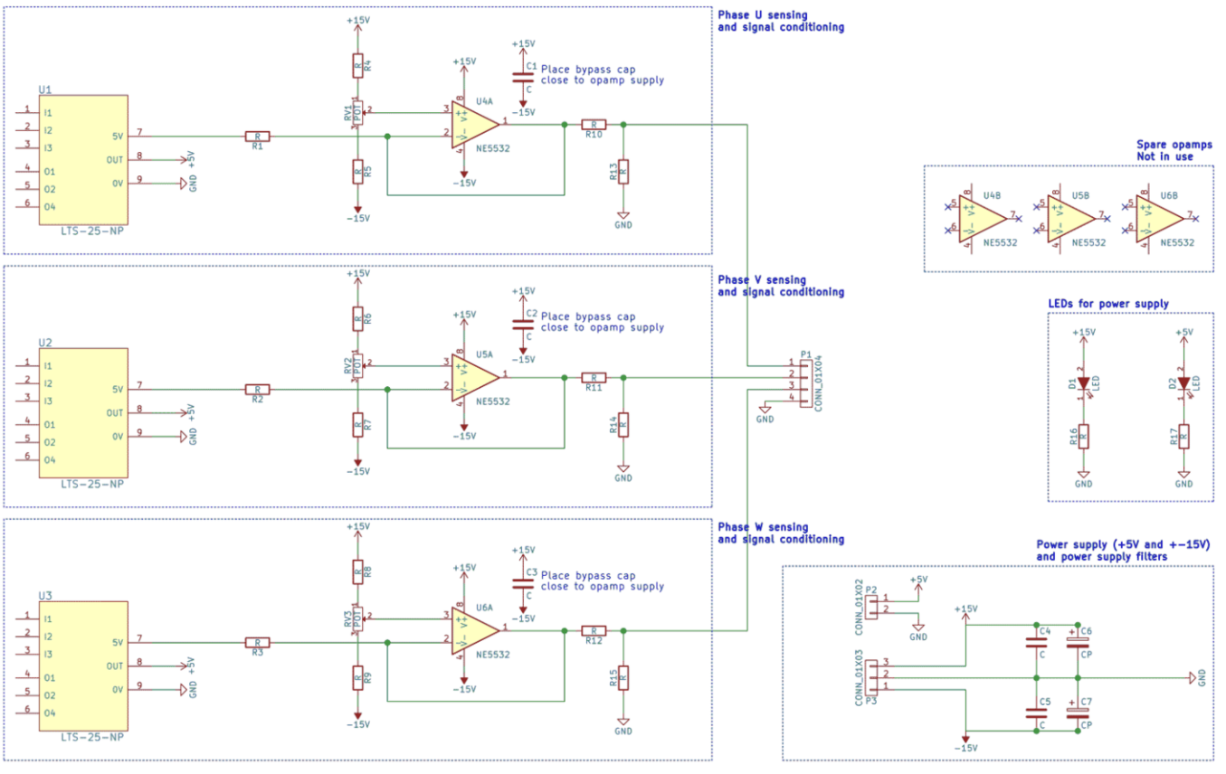
The detailed introduction of the Hall measurement principle in the article only provides some images and schematic diagrams. The current sensor can measure nominal currents up to 25 A and peak currents (e.g. during short circuits) up to 80 AThe dedicated current sensing card has three such sensors and three auxiliary circuits to regulate the signal.Potentiometers are used to fine tune measurements and eliminate any offset.
Due to the current sensor requiring a working voltage of 5V and the operational amplifier requiring a voltage of+-15V, a separate power card is needed to provide two power supplies (I will immediately attach it once the design is ready).The logic and way of thinking are very similar to those introduced in the step-by-step guide for voltage sensing cards, so let's take a direct look at the schematic diagram.Please note that the output stage is represented according to European standards: U, V, and W for stages 1, 2, and 3.
Sharp readers may notice the lack of resistance in the feedback of the operational amplifier.This is because it is used as a buffer, i.e. to replicate the voltage signal from the current sensor without imposing a significant load on it.
I also added two LEDs to indicate the power supply voltage of the two power sources.Besides, compared to voltage sensing cards, there are no surprises here.
The most difficult part this time is actually the PCB layout.The routing path and placement of component footprints are indeed a challenge, and before finally cracking the code earlier today, the editor spent about 10 to 15 attempts.
