The difference between closed-loop Hall and flux gate - Weikewei
. Today, it introduced two other schemes: closed-loop Hall scheme and flux gate scheme.
Closed loop Hall current sensor

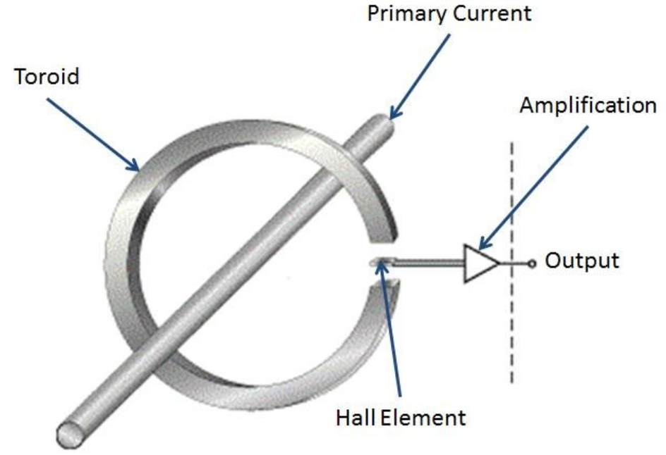
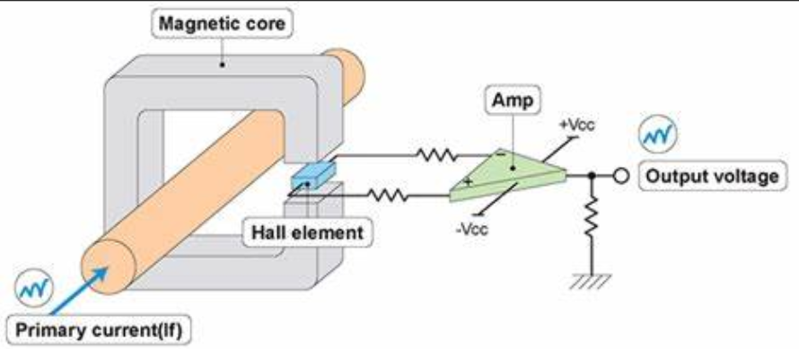
The following figure shows the structure diagram of the open-loop Hall current sensor mentioned above. After establishing a magnetic field in the magnetic core with the measured current IP, the current value is measured by the Hall voltage induced by the Hall element; It outputs voltage analog signals to the outside.

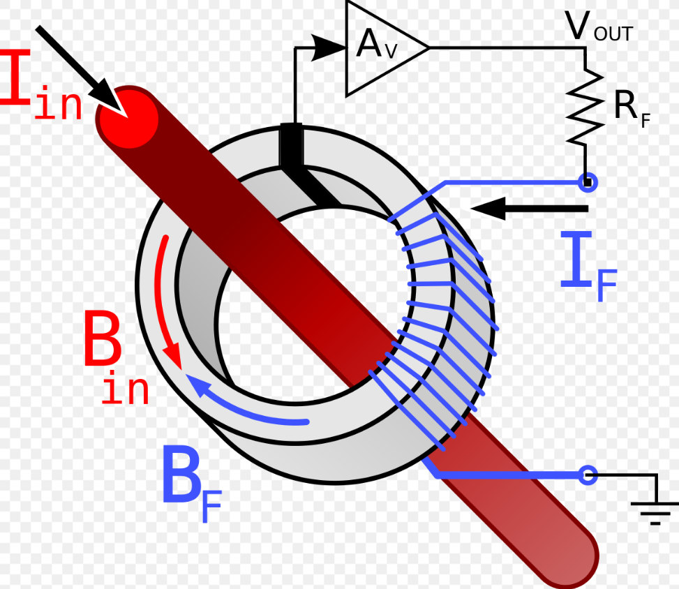
The closed-loop Hall current sensor is based on the open-loop principle and then introduces a compensation circuit. The current flowing through the magnetic core consists of two parts: the primary side current to be measured and the secondary side compensation current. The primary measured current refers to the large current flowing through the copper busbar of the battery, and the secondary side compensation current is generated by a closed-loop Hall current sensor and flows through the secondary side coil on the magnetic core.
Specifically, the Hall voltage induced by the Hall element is not directly used for measurement, but rather generates a secondary current after the Hall voltage passes through the amplification circuit. The secondary current flows through the coil wound around the magnetic core and then through the sampling resistor RM to the ground. In this way, the secondary side current will also generate a magnetic field in the core, and this magnetic field is designed to be opposite in strength to the magnetic field generated by the current to be measured on the primary side. The total magnetic flux is 0, indicating that the Hall element is in an environment with zero magnetic flux.

58彩票Next, when the magnetic flux in the Hall element is 0, the following formula can be obtained. By measuring, IP can be obtained; NS is usually 1000-5000, approximately 25ma-300ma.
Fluxgate current sensor is a product we often encounter. For example, LEM's cab series flux gate current sensors can be divided into several types, as shown in the following figure: standard type, C-type, IT type, low-frequency type, etc. Here we introduce the basic principle of a standard flux gate.
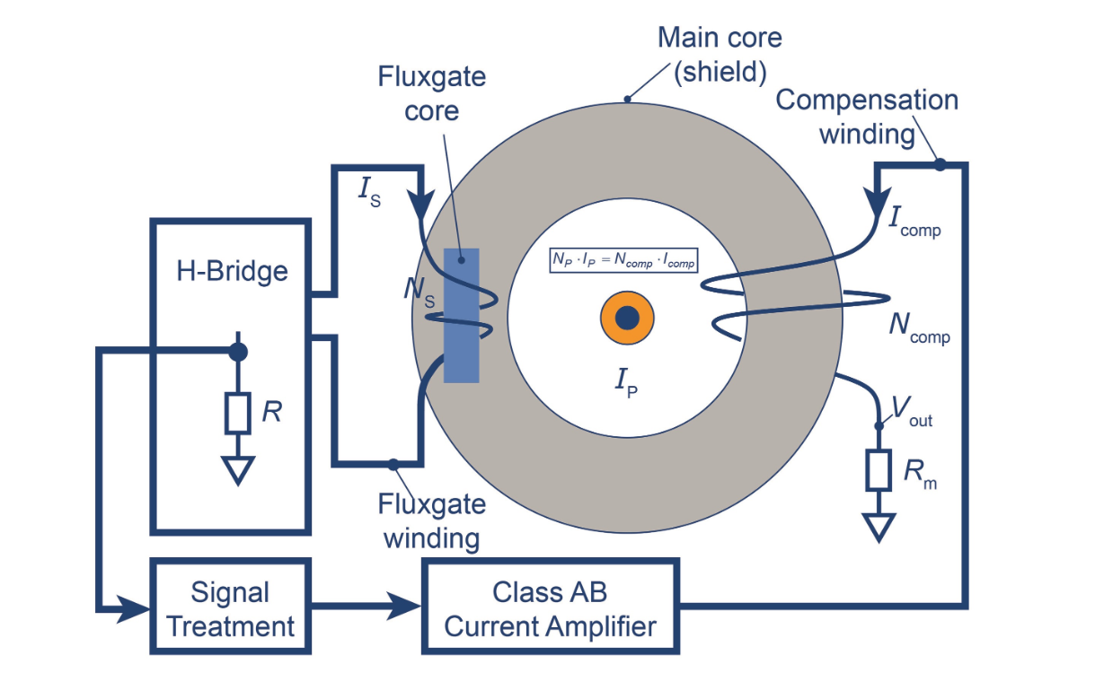
58彩票The structure of a standard flux gate current sensor is similar to a closed-loop Hall structure, as shown in the following figure. Placing only one flux gate sensor in the air gap of the magnetic core will cause the inductance to saturate.
Specifically, in this structure, there is also a primary side current IP (current in the bus) to be measured, and the secondary side feedback current is (in the secondary side coil). Similarly, as long as the total magnetic flux in the air gap is 0, IP can be calculated according to the following formula:
The principle diagram of this scheme is as follows: Firstly, we know the method for calculating the current Ip, which is to adjust the secondary current Is so that the total flux of the air gap is 0, and then we can obtain IP. So, how can we detect the magnetic flux at the air gap in real time and adjust it to 0? In this article, a saturable inductor is used as a probe to identify magnetic flux in the air gap. It is an inductive probe composed of a magnetic core and a coil.
In addition, the magnetic flux at the air gap will affect the inductance of the probe (the probe's inductance is affected by external magnetic fields). We only need to distinguish between inductance when the magnetic flux is 0 and inductance when the magnetic flux is not 0.
So how to identify inductance under different magnetic fluxes?

One solution is to apply current ISI (voltage source U (T)) to the coil of the induction probe. The generated magnetic flux and the total magnetic flux of the external air gap (including the magnetic flux caused by IPI) are superimposed on the magnetic core of the induction probe. The accumulated magnetic flux will affect the inductance of the inductive probe, and the inductance is related to the current. It is possible to know how the current of ISI is affected by the magnetic flux at the air gap.
58彩票Omitting some theoretical analysis processes in the middle, when the total magnetic flux at the air gap is 0, the following figure shows the current in the induction probe, where the dashed line represents the square wave voltage U (T) applied to both ends of the probe, and the solid line is the current value I (T).
58彩票When the total magnetic flux at the air gap is not zero, the current waveform in the induction probe is as follows: Therefore, by detecting the current value, we can determine whether the total magnetic flux at the air gap is zero, and then adjust the current in the secondary coil to make the total magnetic flux at the air gap zero.

Weikewei Technology has been focusing on the localization of imported brands for 12 years, and our professional FAE team can provide you with a range of services电流传感器Free alternative upgrade solutions are available, please contact our technical team for details.
Li Gong: 18576410868