Current sensor output current signal - loss reduced by 37% - [Vickers]
In modern industrial control systems, 4-20mA current sensors are still one of the most commonly used methods for transmitting data between on-site control centers and sensors/actuators. This is because they are easy to use, install, and maintain.Current sensor outputs current signalThe history of pneumatic signals began with the use of pneumatic signals to control actuators and represent proportional control in early industrial automation sites. A typical pressure level is between 3 PSI and 15 PSI, where 3 PSI represents zero scale input/output and 15 PSI represents full scale input/output. If the pneumatic pipeline ruptures, the pressure will drop to 0 PSI, indicating a fault condition that needs to be resolved. Once electronic devices become ordinary pneumatic circuits, they are replaced by 4-20mA current circuits generated by amplifiers, transistors, and other discrete electronic components.
58彩票You may ask, "Why use a current loop?" Well, Kirchhoff's law states that current is constant in a closed loop. No matter how far the current is in the loop, the current is constant. Of course, this requires sufficient loop voltage to maintain Ohm's law. Similar to pneumatic systems, wire breakage or disconnection can cause the loop current to be 0 mA, or a "zero dead" fault state that must be resolved. In addition, current circuits are often relatively easy to protect against electrical transients and have inherent resilience to radio frequency interference (RFI) or electromagnetic interference (EMI) interference [2].
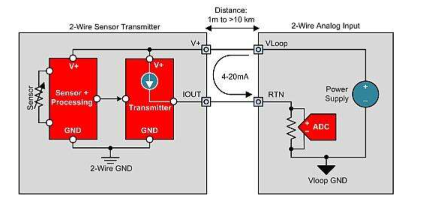
The most common type of 4-20 mA transmitter is a two-wire topology or a two-wire sensor transmitter (Figure 1).
Simplified 2-wire 4-20mA sensor transmitter with 2-wire analog input module
The dual line sensor transmitter is used to transmit physical parameters from the field back to the analog input module for processing and control. Examples include pressure, position, temperature, liquid level, strain, load, flow rate, composition/contamination. As the name suggests, this transmitter only has two wires. Therefore, the sensor receives power from the same two wires that transmit 4-20mA signals, thereby determining one of the main design requirements for a dual wire 4-20mA transmitter. The working current consumed by sensors, sensor adjustment circuits, and 4-20 mA transmission circuits must be less than 4 mA, otherwise the transmitter cannot output a 4 mA zero scale level [3].

Please note that VLOOP GND is not one of the two connections provided to the 2-wire sensor transmitter. Therefore, the transmitter must establish a local ground (GND) or 2-wire GND. When the output current of the transmitter changes the voltage at the receiver circuit (RTN) connection, the 2-wire GND must float up and down relative to the VLOOP GND [3]. If the sensor can be electrically connected to a voltage potential relative to VLOOP GND, isolation is required. This situation is common in thermocouple sensor transmitters, as thermocouples typically experience both thermal and electrical short circuits simultaneously with the material being measured for temperature.
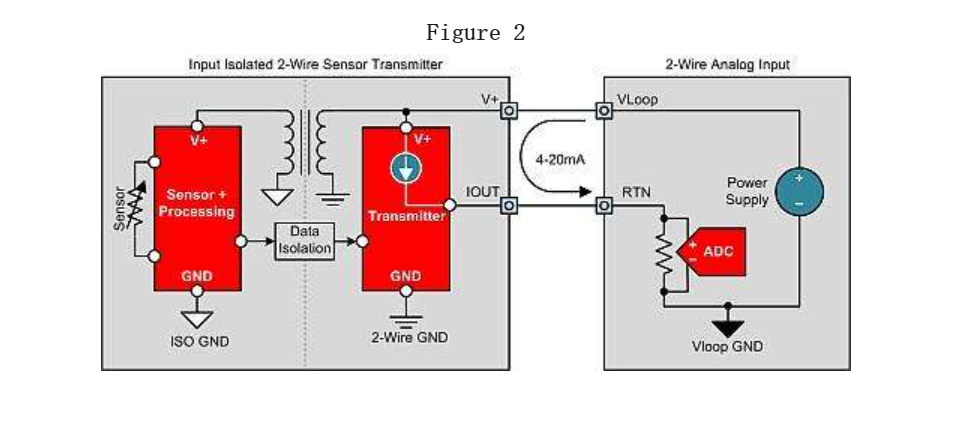
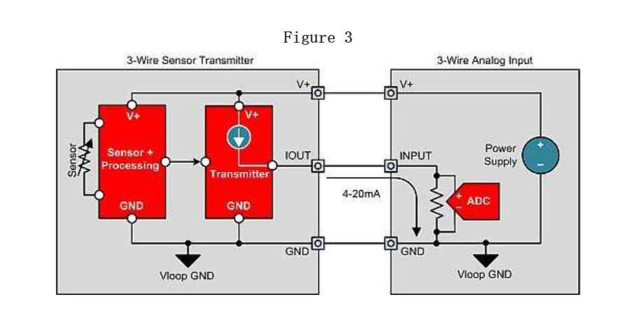
There is only one possible isolation topology for 2-wire transmitters: input isolated 2-wire transmitters (Figure 2). The input isolation 2-wire transmitter generates local isolation power from the loop power supply, which supplies power to the sensor, sensor regulation circuit, and isolation signal method. The digital isolation of pulse width modulation (PWM), single line or serial peripheral interface (SPI) signals is the most commonly used method for transmitting data to the transmitter output stage through isolation gates. As mentioned earlier, the 2-wire sensor transmitter is limited mainly because the power consumption of the entire sensor transmitter must be less than 4 mA. This prevents the use of many types of sensors, including low resistance bridges (such as 100 Ω, 120 Ω, 350 Ω), without limiting the bridge current, which can reduce the sensitivity and accuracy of the bridge. The topology structure of the 3-wire sensor transmitter (Figure 3) supports sensor transmitter designs that require a working current greater than 4 mA.
The three wire sensor transmitter receives power and ground connections from the three wire analog input module to support the power requirements of the sensor and regulating circuit. This allows the sensor power to be as high as possible without affecting the sensor output range (while maintaining Ohm's law). This also enables the 3-wire transmitter to generate 0-20mA and 0-24mA outputs, which are other common output current ranges. Three wire sensor transmitters can also be used.

