Non contact current sensor, [Wickway], TMR tunneling magnetoresistance technology
58彩票Current sensors are often used to provide necessary information for automation control systems and serve as the primary controller in relay logic schemes. The two most common types are current sensors and current switches.
58彩票The current sensor converts the monitored current into a proportional AC or DC voltage or milliampere signal. These small devices have extremely low insertion impedance. Inductive sensors are two-wire, self powered (0-5 VDC or 0-10 VDC output) or loop powered (4-20mA output) instruments, making them easier to install. Hall effect sensors are typically four wire devices that require a separate power supply. Since both types can be directly connected to data systems and display devices, they are ideal choices for monitoring electric motors, pumps, conveyors, machine tools, and any electrical loads that require analog representation over a wide range of currents.

Variable frequency drives (VFDs) save energy and improve motion control through improved motor speed regulation. The thyristor rectifier (SCR) extends the lifespan of the heater by minimizing thermal cycling. Switching power supplies are small, efficient, and compact devices that can be easily integrated with various electric devices. All three technologies are based on high-speed switches, which can cause distortion of the AC sine wave. Understanding the two main methods of current measurement can help you specify suitable equipment for these demanding applications.
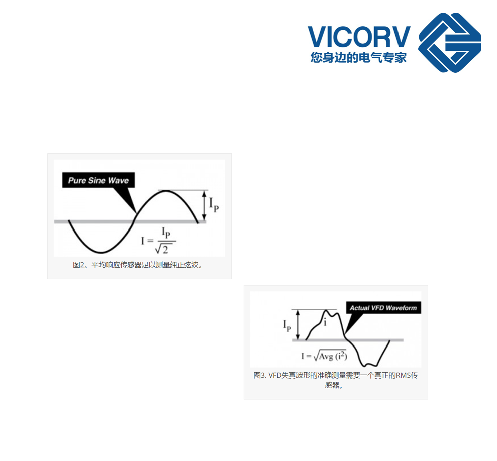
Most current sensors belong to the average response type, which rectifies and filters sine waves to obtain the average peak amperage. To calculate the RMS current of a pure sine wave, the sensor only needs to divide the peak current by the square root of 2 (1.1414). This method provides fast response at a moderate cost (100 · 200 ms), but is only applicable to pure sine waves (see Figure 2).
58彩票The output waveform of a typical VFD or SCR is not a pure sine wave. Simulated waves can exhibit peaks several times larger than the average current, and their relative magnitude varies with the carrier wave and output frequency. In these applications, the average response transducer may be accurate at 20 Hz, but it is 10% high at 30 Hz and 10% low at 40 Hz. The average response transducer is simply unable to provide accurate measurements of these distorted waveforms.
58彩票Only true RMS measurement can accurately measure non sinusoidal waveforms on VFD, SCR, electronic ballasts, switching power inputs, and other nonlinear loads. The True RMS instrument can measure the power or heat generation of any current or voltage waveform. This allows for the comparison of very different waveforms with each other and with equivalent DC (heating) values.
58彩票True RMS measurement begins with squaring the input waveform to mathematically correct the signal. The next step is to average the waves over a period of time and calculate the square root. The output is the true power (heat generation) of the wave (see Figure 3).
58彩票How to determine if you have a genuine RMS sensor? If the product specifications or data sheet describe the output as' true RMS of sine waveform ', then you will have an average response sensor and a clever specification writer. The true RMS sensor specifications will be described in the data sheet as "true RMS for all waveforms" and "accurate measurement of VFD or SCR". True RMS sensors typically provide slower response than average response sensors (400 · 800 ms) and may be 30% · 50% more expensive than average response sensors.
58彩票Most current sensors have solid or split core configurations for easy installation. A typical sensor uses a field adjustable potentiometer. More advanced equipment has a range of jumper options, eliminating calibration work. A typical sensor range is 0-2 A to 0-2000 A, with an aperture of 0.5 inches to> 3 inches (12-76 millimeters).
Current switch. The current operated switch is designed specifically for monitoring and switching AC and DC circuits, integrating current detection and signal conditioning functions as well as limit alarm functions. When the current level sensed by the limit alarm exceeds the user selectable threshold, the switch output is activated. Inductive current switches typically have solid-state output switches. They are self powered, making them a good choice for renovation, refurbishment, and temporary monitoring (see Figure 1). Hall effect current switches have solid-state or relay outputs. Their high power requirements hinder self powered designs, while separate power requirements increase their installation costs.
58彩票Some current switches come with a fixed set point at the factory. Newer designs provide field adjustable set points through potentiometers and LED or LCD feedback. Their set point range is 0-5 A to 0-2000A. For relay logic systems, switches should be equipped with integral delay to allow for start-up surges and instantaneous dips or surges.