Optimization of Current Sensor Inverter Circuit - Weikewei - Protection Response Fast to 1us
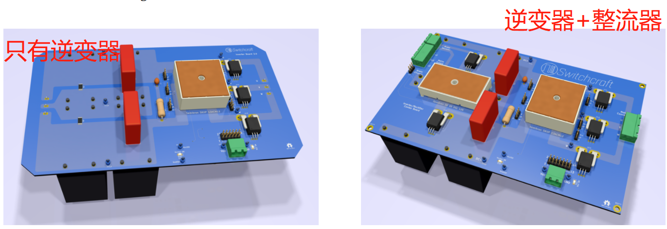
58彩票Last week, Wei Kewei's engineers made a brief update on the status of a certain inverter board. Since then, a three-phase full bridge rectifier and DC+and DC - current sensors have been added to the same board for measurement. The motivation for pursuing this possibility is that there is a large amount of available space on the upper part of the circuit board, directly above the DC connection capacitor. This is a waste of space, so we found a way to put the rectifier into the final result as shown below at the beginning of the work. The printed circuit board must be raised by 1 millimeter to fit completely, and chamfered corners have been removed to make room for screw installation.

58彩票The new circuit board now includes:
58彩票Three phase full bridge diode rectifier (Semikron SK 95 DGL 126) based on SiC transistor module (Semikron Skip 13ACM12V18) with discharge resistor DC connected capacitor (Panasonic EZPE80506MTA, 50 uF) buffer circuit: five current sensors (motor current and DC power supply current), DC circuit voltage measurement, brake resistor connection, seven gate driver connectors (6 for main inverter+1 brake chopper), as shown in the schematic diagram.
58彩票With all these features in place, this PCB can replace the four different cards previously used. Previously, we designed and produced a dedicated PCB for high-voltage measurement, a PCB for three-phase current sensing, a diode rectifier board, and an inverter board. The experience of these projects is now being used to improve all four schematics and place them on the same PCB. This is a remarkable feat, as all electrical connection routes have closely mixed signal traces of both high power and high voltage. When connected to a 690 V power source (offshore/offshore), the DC link voltage can reach up to 1000 VDC, but in a 230 Vac laboratory, the DC voltage is only about 325 VDC. It is very important to establish a low inductance path between the capacitor and the main transistor switch when it comes to wiring on the inverter PCB. Before proposing a complete solution, his work and troubleshooting were documented in the document, so be sure to read it before starting any PCB inverter design of your own. This time, I replaced traditional traces with regions to maximize the electrical cross-sectional area between capacitors and switches, as well as between switches and motor outputs. I hope this will lead to high power consumption with low inductance/resistance.
For more detailed design, please contact the technical personnel of Weikewei.
Li Gong: 18576410868